|
Basic layout.
|
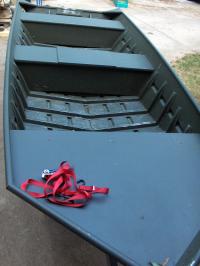
Boat has the conventional 2 bench and bow deck design so commonly seen on factory jon boats. The desired layout isn't going to allow for the keeping of the two bench seats, so they have to go. Furthermore, the owners want the decks raised higher than the existing bow deck, so it will actually be built up, to just under the top of the gunwales, which is the highest allowed in many tournaments.
|
|
|
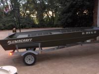
Riveted 1648 Alumacraft, on a galvanized trailer.
|
Here's what we started with.
|
|
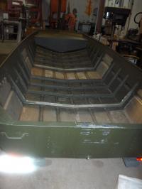
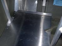
Benches removed.
|
Removing the rivets is done simply by using a sanding disk on a 4.5" angle grinder to sand the rivets flush, then using a hammer and pin punch to knock them out. This doesn't egg out the hole as drilling rivets out often does, and will allow the same size replacement rivets to be used, as opposed to stepping up a size, which won't match the rest of the factory rivets.
|
|
|
There are no factory ribs underneath the bench seats. Therefore, I have to make replacements. These are simply made from aluminum tube, with sheet stitch welded on, to form the riveting flange. Welding the ribs right to the thin bottom of the boat (riveted boats tend to run a good bit thinner than welded jon boats), would cause too much distortion, and mess up the shape of the boat. The rib can be built benchtop, clamped to a strongback, then merely riveted in, without stressing the boat.
|
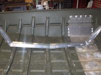
New ribs.
|
|
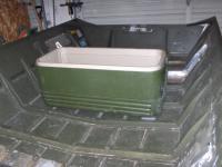
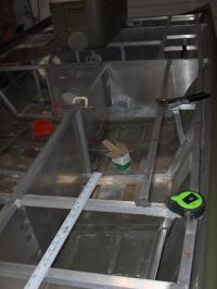
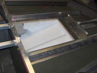
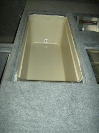
Cooler livewell.
|
A cheap but effective way to install an insulated livewell into the boat is to merely build a cooler into the deck. This shows the approximate placing of the tank, when all is said and done.
|
|
|
As the cooler isn't the same width as the rib distance, I'll be needing deck supports in between the ribs. 2 of these saddles will give me the necessary structure needed to tie a leg into.
|
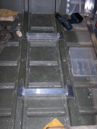
Saddles.
|
|
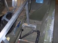
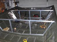
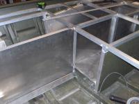
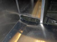
More bridges.
|
Back near the aft part of the transom, I needed a set of bridges to support two more legs. I don't weld any of my structure to the boat, when working with riveted boats, so these too have flanges for riveting into the ribs. Some of the stuff pictured is just tacked in place, at the moment.
|
|
|
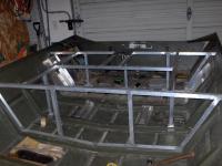
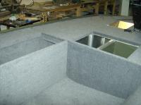
Cooler mocked up behind the beginning of the aft deck structure. If I remember correctly, everything is merely tacked in place at the moment. For once, the cooler actually happens to be a perfect fit underneath the desired deck height (and by perfect, I mean less than 1/8 of an inch off). My luck generally doesn't work that way.
|
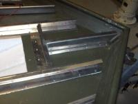
Beginning of the aft deck structure.
|
|
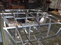
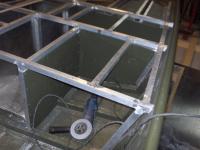
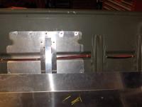
More deck support.
|
Another layer of deck support. Clearly, I generally build transversally, working with the ribs, then tie together with the lengthwise structure. No real advantage or disadvantage to either method, however.
|
|
|
Here is a bit more of the stern deck structure. Not finished at this point, but it's starting to take shape.
|
A little more stern deck structure.
|
|
Stern deck.
|
Can't really see too much in this picture, as everything is piled all over the boat, and my cheap camera doesn't really know what to focus on. None of the other pictures turned out well at all, so this is all I've got, photo wise.
|
|
|
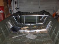
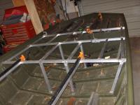
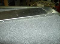
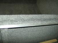
The simplest, most cost effective way to raise the bow deck a matter of inches was to simply bend sheet, and rivet in place. I had some guys at a shop down the road brake the .125 sheet into these shapes. The factory deck sloped forward and to the middle, so to level the deck off with the rest of the boat, each piece was tapered differently from one another.
|
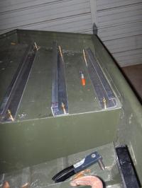
Bow deck.
|
|
Inside of the rod box.
|
Little bit of the rod box structure. Fairly bad picture, I know.
|
|
|
A bit more of the structure, clamped and tacked in place.
|
More bow deck structure.
|
|
Side panel of rod box, and battery hatch floor.
|
The flange at the bottom of the rod box panel will provided support for the lower deck. The simple flange is a quick and easy way to provide support for the side of the deck panel, without building complicated support structures.
|
|
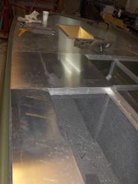
I had horrible luck with the remainder of my structure pictures (including the rod box), so we have to skip along to the paneling underneath the bow deck. The cavity where the grinder is seen will be for general storage, while the area on the other side of the bulkhead will be for the one battery that runs the bow mount trolling motor. Some panels are green, as I reused the factory bench seats.
|
Storage hatch.
|
|
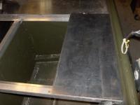
Floor.
|
Got the shop down the road to bend the lower floor, as a piece of this size is past the capacity of my brake.
|
|
|
This flange provides all the necessary stiffness for the side. Also seen is the wiring.
|
Flange and wiring.
|
|
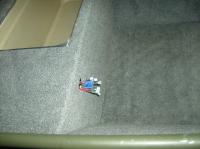
Hole.
|
My pedal trays are deeper than the gap between the factory deck and my deck allows, therefore some of the factory deck had to go. As you can see, there is plywood under the factory deck, as is so often the case.
|
|
|
Just another formed support for the bow deck.
|
Center bow support.
|
|
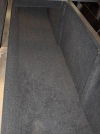
Rod box carpeted.
|
Carpeted the rod box. The carpet we are using is a 16 ounce marine carpet.
|
|
|
Just a couple rods in the box to show the approximate size. This also shows that I use lefty reels, so if someone has the burning desire to donate some Revos or Vientos to me, be sure to pick up lefty models....
|
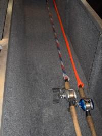
Couple rods in the rod box.
|
|
Deck pieces.
|
Deck pieces, laying in place. All my decking is .125 aluminum, 5052 alloy.
|
|
|
This piece covers up the area immediately beside the storage hatch lid.
|
Starboard deck piece.
|
|
Fuel tank/battery floor.
|
Simple floor to support the fuel tanks or batteries, depending on how they are running at a given point in time.
|
|
|
This simple formed mount raises the trolling motor up to the height of the gunwale. As there is no back access to mount fasteners, this bracket has aluminum plates, drilled and tapped for the mounting bolts, attached to the underside, in place of nuts.
|
Trolling motor mount.
|
|
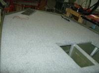
A little carpet.
|
Just some carpet. It is always a royal pain in the neck, but the end result is a very clean and finished look.
|
|
|
This shot also shows the layout of the back deck much more clearly than the earlier photos do.
|
Bit more carpet.
|
|
Lid support.
|
All the hatch lids are supported by these lips, which consist of aluminum angle. The carpet is finished in this manner.
|
|
|
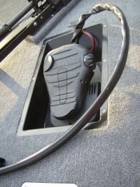
Another shot of the carpet. Have one of my dummy trolling motor pedal trays filling the hole, as I kept having to fish out tools I would drop down the hole. The actual tray is powder coated black.
|
Bit more carpet.
|
|
Livewell.
|
Cooler installed. There is a drain fitting on the starboard side. An aerator will be installed, and for filling, the owners will keep a pump with a short section of hose, which will plug into a 12 volt accessory plug.
|
|
|
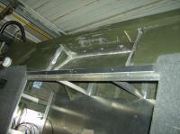
Splashwell installed. It was also made from the factory bench seats, hence why it is already green.
|
Installed.
|
|
Switch panel wiring.
|
Switch panel and 12v accessory plug will be installed here.
|
|
|
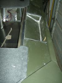
Because the boat has a short (15") transom, and the decks are built at gunwale level, the stern deck is actually higher than the transom. To finish it off nicely, a splashwell was built. Being a short transom boat, having a splashwell that is self bailing will probably be desirable while fishing in rough water.
|
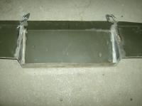
Splashwell.
|
|
Another angle.
|
Another angle. There will be a drain hole.
|
|
|
Terminal block is made from scrap phenolic, with brass hardware. 4 fuses for: nav lights, sonar, 12v accessory plug, and livewell aerator.
|
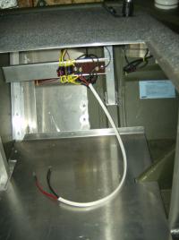
Terminal block/fuse panel.
|
|
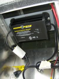
Onboard charger.
|
While the 3 batteries that power the 36v transom mount motor are removed and replaced often, depending on the lake of choice, the battery for the bow mount trolling motor will stay installed at all times. Therefore, the owners wanted this single bank onboard charger installed. Minn Kota recommends that these are electrically isolated from an aluminum boat, so I mounted this one on a piece of HDPE (High Density Polyethylene).
|
|
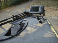
These trays are just about essential these days. This allows one to stand level, eliminating balance issues, and allows one to be much more comfortable, as opposed to having to stand with the "Captain Morgan" stance.
Trays are made from 5052 aluminum, TIG welded, then powder coated black.
I happen to fabricate and sell these, and can ship nationwide. Email dmion (at) comcast (dot) net, if interested.
|
Trolling motor pedal tray.
|
|
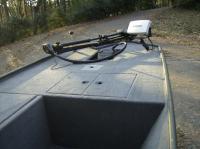
Finished.
|
Finished boat. Bow mount trolling motor is a Minn Kota Edge, 55 pound thrust. Sonar is a Humminbird 898c, which is has the capabilities of: side imagine, down imaging, conventional sonar, and GPS.
|
|
|
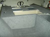
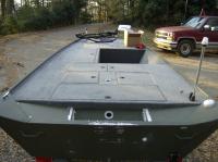
View of the stern deck.
|
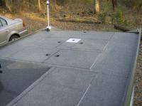
Stern deck.
|
|
Bow deck.
|
Another shot.
|
|
|
The owner will paint the splashwell, to eliminate the welded areas.
|
Entire rig.
|
|