|
Starting point
|
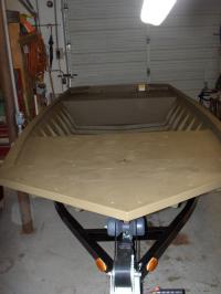
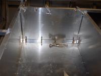
Here is what we started with. A new G3 1652 all welded.
|
|
|
Another angle.
|
Starting point
|
|
Starting point
|
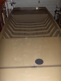
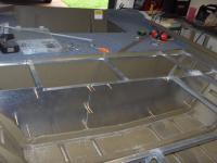
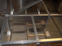
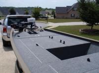
Shot of the bow deck. Notice it has a storage cubby extending underneath.
|
|
|
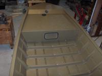
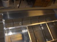
The bench seat and side seat pods are factory welded in. The stern lid is available as an option, which the owner decided to get. It comes in a box, uninstalled. The picture shows it resting in it's future home.
|
Stern lid
|
|
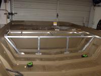
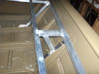
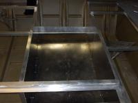
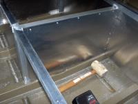
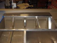
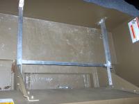
Stern deck structure
|
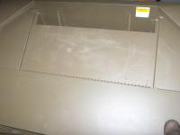
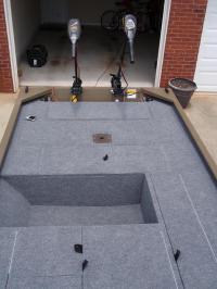
Owner wanted the stern deck to be extended forward to the second visible hull rib (approximately 16" forward). It is split into two storage hatches.
|
|
|
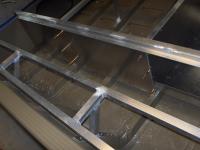
Another view. Structure is TIG welded, using 1 x 1 aluminum tube, supplemented by 1 x 1 aluminum angle, as the structure is fastened to the ribs with rivets.
|
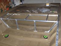
Stern deck structure
|
|
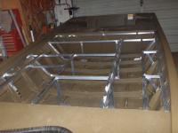
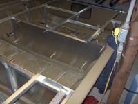
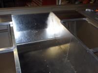
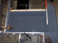
Completed deck structure
|
I failed to take pictures of the construction of the rest of the deck structure, but here we see it completed. A closer look reveals two layers of structure. As the deck itself will be .125 aluminum, yet the lids, once the flanges are made, will be approximately 1 inch thick, a multilevel deck structure is required to keep everything flush. The hatch lids are hinged from the edge, requiring 3 sides of the lid to be supported by the bottom tier, with one side at the upper level.
|
|
|
Another angle of the deck structure. The long hatch on the port side will be the rod box. Rod tubes will extend forward into the bow deck. The square hatch amidships will contain 3 of the six batteries this boat will run. The open space on the starboard side/middle will be a lower deck. The owner doesn't fish many tournaments, thus a permanent livewell would be a waste of space much of the time. Thus, we decided to leave a section of lower deck, where a portable livewell or a cooler can be placed, depending on the desired use.
|
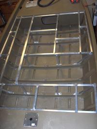
Completed deck structure
|
|
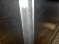
Side deck support
|
We didn't want a leg interfering with the storage space, thus the support needed to attach further up the rib.
|
|
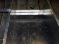
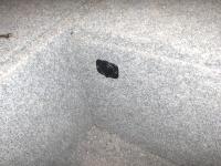
Oooh, fun. I get to play with some carpet now. I doubt it is visible in the picture, but the owner wanted the carpet to extend up to the bottom of the gunwale, as this keeps high dollar reels from being scratched and banged up when they are laid near the edge.
Also, there is a thick rubber anti fatique runner glued under the carpet. This really helps take some of the impact off ones joints when fishing in a light chop.
|
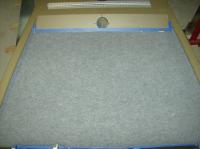
Carpeted bow deck
|
|
Stern deck face
|
Back to some metal fabrication. Have to throw some carpet work in here and there, else I have too much fun otherwise.
Panel is made from .063 aluminum sheet. Currently held on with Cleco's.
|
|
|
Panel, made from .063 aluminum again, held in with cleco's at the moment.
|
Bow deck face
|
|
Lower deck
|
Lower deck was fabbed from .090 aluminum. A brake bend at each side gives it significantly more rigidity than the flat sheet would have alone. Obviously, running the piece all the way up the side would have been nice, but it wouldn't be a very efficient use of material, and would require the customer to buy another whole sheet, of which only a small portion would be used.
|
|
|
Here we have the bent flange at the port side, where the rod locker bulkhead will be.
|
Lower deck
|
|
Rod locker forward bulkhead
|
Here is the forward bulkhead for the rod locker, which separates it from the battery hatch, and the forward middle storage hatch.
|
|
|
As opposed to running another vertical leg here, which is unnecessary from a structural standpoint, I used the brake to bend a mounting flange at the front of the bulkhead.
|
Forward mounting flange for rod locker bulkhead
|
|
Rod locker aft bulkhead
|
The structure design needed the rod locker wall to be stepped, and thus installed in two sections. Here is the aft section. There is a mounting flange bent at the bottom, as well as each side of the back.
|
|
|
Here we have the starboard battery hatch bulkhead.
|
Starboard battery hatch wall
|
|
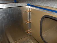
Forward starboard corner of battery hatch
|
Here we have the corner where the starboard and bow faces of the battery hatch meet. Because this outside corner will be exposed in the finished storage hatch, I decided to bend a flange in each panel, and attach to the other side of the leg, as opposed to merely meeting them on the outside, where they could easily snag and rip tackle bags, PFDs, knuckles, etc.
|
|
|
Forward panel of the battery hatch.
|
Forward panel of battery hatch
|
|
Starboard deck
|
The owner did not want the hatches hinged at the edge of the boat, as when rods are laid on the deck, they interfere with hatches opening. Thus, a narrow section of deck is required, port and starboard.
|
|
|
Port side deck.
|
Port deck
|
|
Starboard side panel/aft side deck
|
Side panel and aft deck.
|
|
|
As the hatch fit them snugly on 3 sides, the 3 forward batteries needed to only be restrained on one side. Thus, I bent a 3 inch flange at the edge of the floor, and TIG welded a gusset on each side, to eliminate any lateral movement.
|
Forward battery restraints
|
|
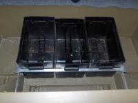
Aft battery restraint
|
This simple frame contains the aft batteries.
|
|
|
Seen here with boxes in place.
|
Aft battery restraint
|
|
A hatch lid
|
One of 7 hatch lids I fabricated.
|
|
|
Hatch is fabricated from .125 sheet, and .75 x .75 angle, as the frame. The nylon loop is the hatch pull. It is pinched between the hatch frame, and the .125 sheet, thus it is a solid attachment, and because it wraps from the inside, doesn't interfere with wrapping carpet.
|
Bottom of a hatch
|
|
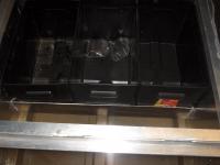
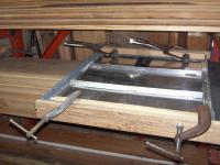
Carpeting the lower deck
|
Clamps and blocks are needed to hold the corners tight and crisp while the glue dries.
|
|
|
Clamps and blocks were also used to fold the carpet around the flanges of the hatch lids. Notice the stiffeners on the bottom of the hatch. Unlike the small lid pictured above, the larger hatches required a stiffener or two to be stitch welded underneath.
|
Carpeting the hatch lids
|
|
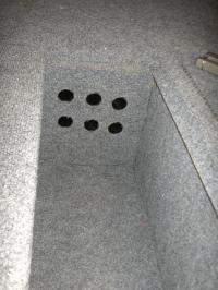
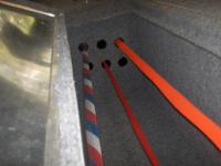
Rod tubes
|
These rod tubes are actually golf tubes, designed to separate clubs in a golf bag. Because they already have a flange at one end, they are perfect for rod tubes. I used a hole saw to cut the holes in the aluminum, then a homemade coring tool, made from a scrap of pipe, to core the flotation foam out. The tube then fits snugly, with a nice tight friction fit.
|
|
|
A white plastic cutting board was used to make a holder for the rod butts. I have 3 of my bass rods modeling the holder at the moment.
|
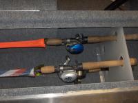
Rod butt holder
|
|
Rods in the tubes
|
Rods in the tubes.
|
|
|
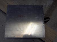
Because the Humminbird side imaging sonar is a pretty heavy unit, and the area underneath the bow has plywood, I didn't trust mere fender washers to not try and pull through. Thus, I made this simple backup plate from a scrap piece of aluminum.
|
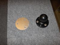
RAM mount backup plate
|
|
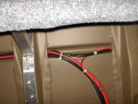
Wiring
|
All the wiring in this rig was run down the port side, through the chine. To reach the midships batteries, the wires were routed underneath the lining for the rod locker.
|
|
|
All the wiring in this boat is marine rated tinned copper. All the lugs and terminals have been completed with heat shrink.
|
Wiring
|
|
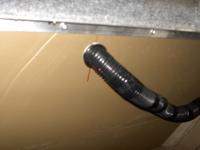
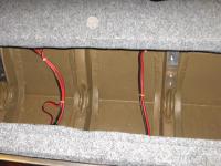
Wiring
|
The wiring had to pass through the aft bench seat. Thus, I used a golf tube to create the passageway through the boat, and wrapped the wiring bundle in loom, to clean the bundle up, and protect the wires.
|
|
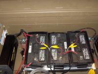
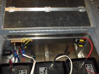
Aft, we have 3 batteries. The two starboard batteries power the starboard transom mount trolling motor, and the port battery, as well as one battery in the forward hatch power the port 24v trolling motor. If you look closely, you can see a relay on each side. The owner wanted to be able to control these trolling motors from the bow. Thus, a "Big Foot" switch will control them. However, due to the amp draw these motors pull, the 10 AWG wire that all these switches have, the current loss would be too great. The run of that length would actually require the use of 4 AWG wire, and the 10 gauge would cause major current loss. "A chain is only as strong as it's weakest link."
Thus, the solution was to use 24 volt continuous duty rated relays. Not only did it eliminate the need to run full power through the mediocre switch, it also shortened the run length drastically, allowing the use of 8 AWG wire on the starboard side, and 6 on the port, as that has the split battery setup.
|
Aft batteries
|
|
Aft wiring
|
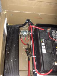
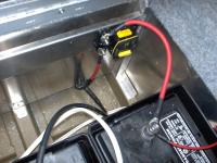
Better shot of the relay and circuit breaker for the port side transom mount trolling motor.
|
|
|
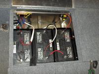
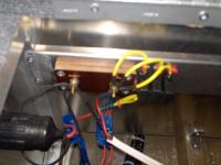
Here we have the forward batteries. The two batteries on the right (forward in the boat) power the bow mount. The 12 volt power for the bilge pump, sonar, and 12 volt accessory plug is taken from the left battery.
|
Forward batteries
|
|
Circuit Breaker for bow mount
|
Circuit breaker protecting the bow mount trolling motor.
|
|
|
A piece of .063 bent into a 'U' makes an excellent mounting surface for the breaker and terminal block, with no exposed sharp edges.
|
Breaker/terminal block mount
|
|
Terminal block
|
Terminal block was made from 2 layers of scrap phenolic, and brass hardware. Bilge pump, sonar, and the 12v accessory plug are powered off this terminal block, and fused just to the right of it. The black thing in the left of the photo is the backside of the 12v accessory plug.
|
|
|
This plug will be used to power the aerator in his portable livewell.
|
12 volt accessory plug
|
|
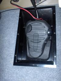
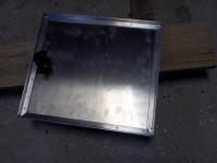
Trolling motor pedal well
|
Here we have the trolling motor pedal well.
I happen to make and sell these pedal trays. They are TIG welded 5052 aluminum, powder coated black. If anyone is interested, my email address is dmion (at) comcast (dot) net.
Shameless plug, I know.
|
|
|
Here we can see the Minn Kota Maxxum mounted, as well as the Humminbird 898c side imaging unit. The two bigfoot switches that control the transom mount motors are just to the right of the trolling motor well.
|
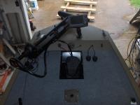
Bow area
|
|
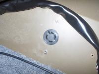
Trolling motor power socket
|
Push and turn power socket for the bow mount trolling motor.
|
|
|
Rocker switch for the bilge pump. Equipped with red indicator light to show "ON."
|
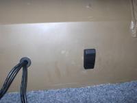
Bilge pump switch
|
|
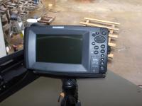
Humminbird 898c sonar
|
Just had to throw in a shot of this sonar, as they are pretty cool. Aside from having a very high resolution conventional sonar, this has both side imaging, and down imaging. The side imaging gives an "image" of the lake floor, as if you were looking down from above, up to 150 ft. on either side of the boat. The down imaging allows a horizontal view of what is directly under the boat, but puts the picture as an "image" as opposed to the typical sonar screen. An accurate GPS fix can be gotten, as well as a waypoint marked at any spot on the screen, even if it is a hundred feet off to the side and back.
|
|
|
Luckily the owner took a few shots of the rig after he picked it up, as I failed to do so while I still had the boat.
|
Completed rig
|
|
Completed rig
|
Another picture, courtesy of the customer.
|
|