|
Before
|
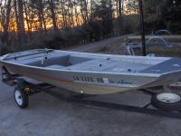
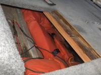
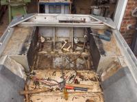
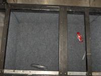
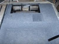
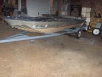
These next few pictures are from before I started. Amazing what a carpet job can hide. The plywood in this boat is a bit rotted (well, very rotted)
|
|
|
|
Before
|
|
Before
|
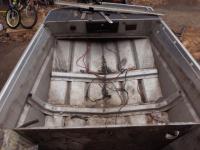
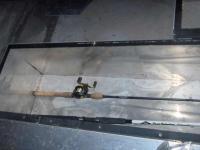
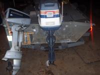
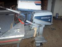
This boat has a 20 inch transom, and a 42 inch bottom width. I just so happen to have a 1974 Evinrude 40 horse long shaft in the shop. A tiller off of ebay has solved that dilemma.
|
|
|
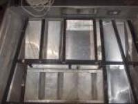
Crude hatch
|
Before
|
|
Before
|
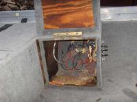
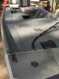
These hatches opened up to the hull. It works, but I have never liked that idea. Stuff gets wet, or lost in the bilge easily, and it doesn't have a clean look.
|
|
|
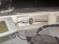
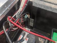
Oh boy. Look at the back of this switch panel. Have to give it to the previous owner though, there was access to the back of the switch panel, and a few of the wires were even labeled.
|
Before
|
|
The stripdown
|
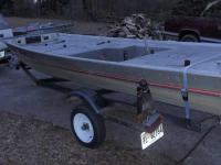
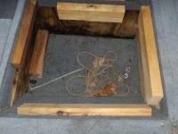
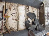
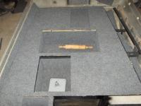
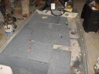
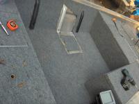
The bow area after stripdown.
|
|
Though the bow deck had many reasons that lead me to believe it had been redone/modified sometime in the middle of the boats life, this lower deck was likely factory. It was actually marine plywood, and held on with stainless fasteners to boot. And, it was significantly more rotted as well. If it wasn't for that foam holding it up, it would have fallen in between the stringers. Also, notice that bulkhead. I wasn't exactly expecting a single bulkhead there.
|
Lower deck removed.
|
|
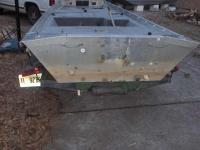
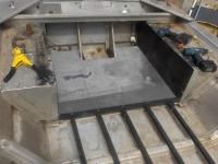
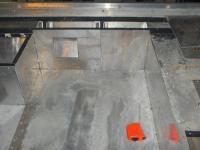
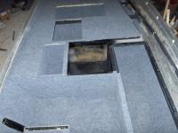
Stern deck removed.
|
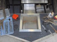
As you can see, I have these stern boxes, that contain foam. They are where my new deck will extend to. As you can see, the old deck extended to the line in the carpet. It was so far forward that you couldn't sit at the front, and still reach a tiller. The previous owner apparently sat upon a pedestal to operate a 40 tiller.
|
|
|
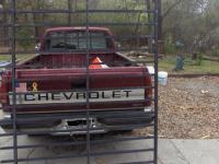
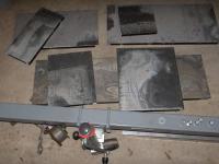
Because of the high aluminum pricing, I am buying used aluminum. It is sold at surplus aluminum price, which at this time, is 2 bucks a pound. These fences yield somewhere around 15 1 x 1 square tubes, with 1/16 wall. Each tube will come to around 75 inches in length, and each section usually sets me back about 75 bucks. I ended up using 3 of these sections to complete the project.
|
Structure material.
|
|
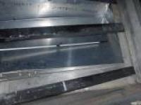
Deck Material
|
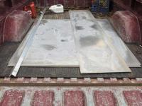
Here is some material I got at scrap price as well. It is .090 thick aluminum sheets of 6061 T6 alloy. Also have a piece of 1 1/2 inch, 3/16 thickness angle for brackets. There are 4 sheets that are 4 by 4.5 feet, and 1 that is 18 inches, by 7.5 feet. What you see here set me back about 250 bucks, and the sheet provided enough material to complete the deck, and hatch lids. For lining the hatches, I have some 1/16 sandwich board, brand new, but scrapped, and some .025 material, again brand new, but scrapped.
|
|
|
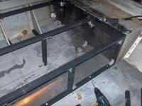
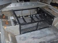
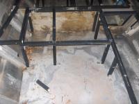
I have started installing the new deck supports. Sure, it raises the deck by an inch, but it makes installation a heck of a lot easier, and gives me a larger bilge.
|
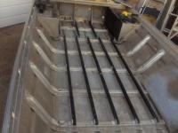
Structure for new deck.
|
|
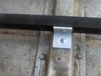
Floor structure bracket.
|
|
|
|
At some of the ends, I cut it at a 45, and stuck a rivet in that way. Made it quicker, and removed the whole bracket idea.
|
|
|
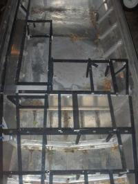
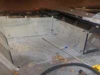
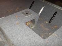
Deck under stern deck.
|
This is the deck that is underneath the stern deck. There will be a fuel hatch and storage hatch back here.
|
|
|
At the current, the structure was held in with rivets that hadn't been tightened yet.
|
Started framing stern deck
|
|
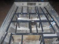
Stern deck framing.
|
I have completed the framing of the stern deck, and as you can see, I have gotten the next section of lower deck installed as well.
|
|
|
In this picture, you can see where the fuel tank, and double seat bases will go. The reasoning behind the double seat bases is to be able to sit low, and off center to drive, but then be in the center to fish off the pedestal.
|
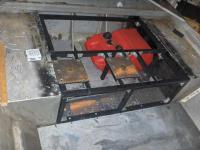
Stern configuration
|
|
Bow structure
|
Unfortunately, I didn't take any pictures of the bow structure during building, but these next few shots show it completed, or almost such (on the starboard side, you see the "gusset" is a cardboard template - hadn't yet made the gusset)
|
|
|
On the far left of the picture, you can see the wiring chase. I have planned it to where you can access all parts of the wiring by just pulling off a cover with a screwdriver. The battery hatch is the one amidships, right beside the rod locker.
|
Bow structure
|
|
Aft end of bow deck structure.
|
The box you see in the middle is the battery hatch. A starting battery and a deep cycle trolling battery will fit in there, within battery boxes. In the top right of the picture, you can see a portion of the wiring chase. To the left of the battery hatch, is my tackle hatch. It is sized to fit the 360 size boxes I use.
|
|
|
I have made a couple of the side panels. They are held on with cleco fasteners at the time of this picture.
|
Side panels.
|
|
Aft end of rod locker
|
Ample space for a number of rods in here. That white one is an 8 foot surf rod, so length is not going to be a limitation, at least as far as bass fishing goes (until I venture into swimbaits at least).
|
|
|
Here is the bow end of the rod locker. That is the other end of the 8 foot surf rod.
|
Bow end of rod locker
|
|
Trolling motor pedal well
|
I have finished fabricating the trolling motor foot well too. I have also completed the boxing in of the bow storage hatches, but due to my computer and camera illiteracy, can't seem to find them.
|
|
|
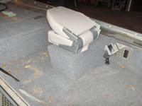
Made the passenger seat, and passenger rod ramp. There is storage underneath the seat.
|
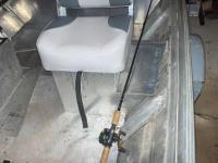
Passenger seat.
|
|
Passenger seat.
|
Here is another shot of my passenger seat and seat box.
|
|
|
Here are a few of the hatch lid frames. They are made with more of the 1 x 1 aluminum tubing, and have 3/16 thick, 1.5 inch angle as corner brackets.
|
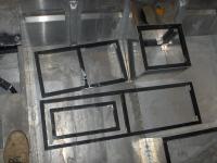
Hatch lid frames.
|
|
Hatch lids
|
Here are my completed hatch lids.
|
|
|
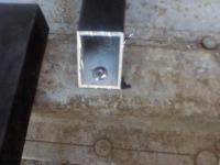
Here is my starboard side panel. The hole is cut out for my switch panel, of which I have back access to through the top of the wiring chase.
|
Starboard side panel, with switchboard cutout.
|
|
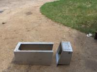
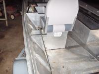
Anchor hatch
|
I have made an anchor hatch out of an old livewell that was in the boat. I cut the end off, and then framed it with 1 x 1.5, 1/16 wall aluminum angle.
|
|
|
Top view of anchor hatch.
|
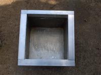
Another shot of anchor hatch.
|
|
(Insert New Caption)
|
(Insert New Description)
|
|
|
Anchor fits in both vertically, and horizontally, leaving plenty of room for the rest of the rode.
|
Anchor in hatch.
|
|
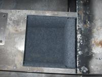
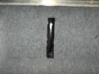
Stern hatch carpet.
|
I have now found a part of the project that I actually hate. Not just dislike, but despise to all ends.
|
|
|
Carpet in back section of rod locker.
|
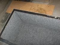
Rod locker carpet.
|
|
Bow storage carpet.
|
Carpet in one of the bow storage boxes.
|
|
|
No, that yellow area is not a piece that is too small. Got to leave room for the hinge. The very front hole is the trolling motor pedal well.
|
Bow carpet.
|
|
More carpet work.
|
Have I mentioned that I HATE carpet work?
|
|
|
On the port side, where ribs were exposed, I decided not to carpet to them, since I will probably use them for tie down mounts and such. Don't want to have to deal with carpet while mounting things. So, I just painted them black, and carpeted around them.
|
Rib.
|
|
Stern deck.
|
Shot of the stern deck, after carpet work. I have forgotten to mention this before. The carpet is Lowes indoor/outdoor carpet, and I am attaching it with Henry 663 carpet glue, which Lowes also sells.
|
|
|
Since I didn't want a livewell in this rig (not a permanent one at least) I didn't want to have plugged up thru hulls, so I made these patches out of .090 aluminum, and sealed with 3M marine 5200 sealant.
|
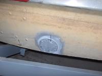
Patch.
|
|
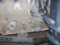
Transom repairs.
|
Had to patch a few thru hulls here as well, as well as thousands of screw holes for transducers, and mounting holes from quite a few motors. The screw holes were patched with pop rivets, sealed with 5200, and the motor holes were filled with a marine silicone.
|
|
|
More patches. Ironically, even with all the holes, I had to drill new ones to get my transducer where I wanted it.
|
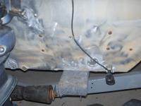
Starboard side transom repairs.
|
|
Hatch lids installed.
|
I am not crazy about the way these turned out, and they will be remade later on. However, the problems are aesthetical, and don't hinder the use, so they will stay for the time being. The uncarpeted area is my wiring chase.
|
|
|
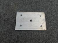
I wanted my trolling motor bolted down, but didn't want to have to pull my anchor locker to reach nuts for removing, so I made this backer out of 1/4 aluminum. I drilled and tapped the two center holes for 1/4 inch bolts to hold the plate in place when the trolling motor isn't in place. The outer holes were drilled and tapped for 5/16 trolling motor mounting bolts.
|
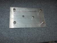
Trolling motor backer.
|
|
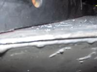
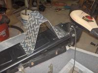
Broken weld.
|
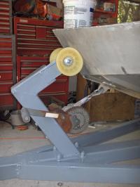
The previous owner had a trolling motor similar to mine mounted up here, and since a majority of the weight is at the head, which is unsupported when stowed, every bounce of the boat twisted the bow upward, which started to crack this weld. Well, I am going to get that rewelded soon, but if I don't support it somehow, I am still going to have the problem of the weld breaking again.
|
|
|
To counter that problem, I made this little support out of some diamond plate.
|
Solution
|
|
Support
|
Because it deploys with the motor, it doesn't take up deck space when the trolling motor is deployed.
|
|
|
(Insert New Description)
|
Pedal in well.
|
|
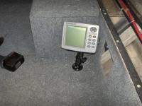
Bow sonar mounted.
|
The bow sonar is an Eagle Fishmark 320 that I picked up off the bassresource.com swap and sell section last year, and ran on my Grumman. Originally, I wanted to mount it on the starboard side, but I figured that when beached, people are more likely to enter from the starboard with the trolling motor on the port, so I mounted it there instead. Still easy to see, but a little safer here.
|
|
|
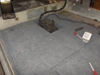
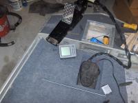
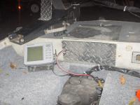
The console sonar is an Eagle Fishmark 480 that I got off the bassboatcentral.com swap and sell section last year, with the RAM mount included. I mounted it on the deck right in front of the drivers seat.
|
Console sonar mounted.
|
|
Repainted trailer
|
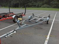
We lengthened the trailer tongue, and also added a diagonal step in front of the fenter (kept slamming knees into the square front of the fender, so we got rid of the square edge). I painted it a smoke gray.
|
|
|
Notice the last picture didn't yet have the winch post installed. The one previously on there was way to bulky, so we made a smaller one instead.
|
Winch post
|
|
Trailer
|
Finally managed a picture of the complete trailer at the ramp while the boat was on its maiden voyage.
|
|
|
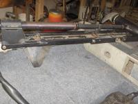
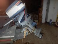
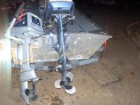
The lower unit on the '74 40 was shot, so we bought a '75 Evinrude 40 off of Craigslist, that the same tiller would fit on. Just to spruce it up, the lower unit seals were replaced, the carb was rebuilt, and the spark plugs, points, and condensers were replaced. The fuel pump and flywheel were swapped over from the '74, as the flywheel on the '75 was cracked.
|
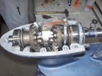
Lower unit rebuild.
|
|
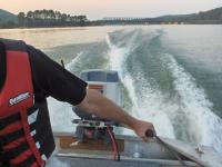
Test run.
|
I got just the trolling motor, and outboard wired, so we went on a test run. Judging by timing a 3 ish mile run, I am estimating that we are getting 28 - 30 mph out of this rig. Don't have a clue what RPM I am turning at this point, so for all I know, I might be able to gain a bit with a different prop. I have a list of minor issues a mile long, but I knew I would, and luckily, they are much more minor than I would have originally thought. Basically, there are some rattles that need some rubber to quiet, and the passenger seat needs a swivel to be more comfortable. Once I finish the rest of the wiring, there is no reason we can't use it as is, and repair the minor stuff as time goes by. I did however, miss filling two screw holes in the transom, so we had a bit of water in the bilge, but they will be fixed ASAP, now that I know they exist.
|
|
|
Having the passenger seat on the side gave me slight trim problems. The boat would sit perfectly level with just one person at the helm, but add a person on the port side, and it would lean a bit. Not much, but enough to drive an anal retentive person like myself slightly nuts. Adding 60 pounds of kicker motor and bracket to the port side would only worsen things, so something had to be done. I decided to move the passenger seat to the center, and leave the port side open for a walk path. Instead of the top opening, I left the front open as a cubby, and put a base to put the pin style seat in. Having the old seat fixed forward was a pain.
|
Center seat moved.
|
|
Completed picture
|
I still need to paint the inside of the cubby, and the now exposed rib, (as well as clean my carpet).
|
|
No, the carpet is not that dirty. The lighting and timing of that picture made it appear real muddy.
In the rest of the boat, I used the stainless pedestal bases. The old ones that came out of the boat had bronze bushings. The one I bought to use up in the bow had a plastic bushing. But, the stainless bases I bought had some form of regular steel for the tube for the pin. I had to paint the base to keep them from rusting. However, I got this base at Wallyworld. It is cast aluminum, but still has the plastic bushing. I do, however, like these aluminum ones much better.
|
Seat base
|
|
Trolling motor wiring connection
|
I wanted my trolling motor to be fairly easily removable, but don't like the trolling motor plugs, as they are notorious for current loss. I got this little block, and to unhook my troller leads, I just have to remove two #10 phillips screws.
|
|
|
I used a piece of diamond plate, and attached it with sticky back velcro to cover the connection. Not only gives it a more finished look, but also gives the safety of not having it out in the open where a dropped lure or something could arc between the + and -, and light the boat up.
|
Wiring connection cover plate.
|
|
New rod holder base.
|
Since I didn't like my other rod holders, I pulled them out, and decided to make my own. I made 6 of these bases out of some 3/8 thickness, 4 inch wide aluminum bar. I drilled and tapped a hole for a 1/2 inch bolt or threaded rod in the middle, and then installed it with 4 3/16 rivets, which I countersunk. I have 1 on each of the 4 corners of the bow deck, and 1 on each side of the stern deck. More to follow on the actual holders later.
|
|
|
I finally got pictures of some of my electrical work. This is my battery hatch, and I have the wiring chase cover removed, so the routing of the wires can be seen. My trolling battery is the green Interstate Group 27 deep cycle. My starting battery is an old AAA starting battery from a Toyota that we inherited, and parted out. It had been sitting on a battery tender in the shop, so I figured I may as well wear it out before buying a new Interstate. That dang car battery has lasted a heck of a lot longer than I thought. Being in the boat, it bounces around a LOT more than car batteries are designed for, and it is about 6 years old to boot. It has been serving me reliably since July, when I got the boat in the water, and I am typing this caption in the end of October.
|
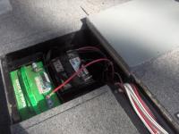
Battery hatch
|
|
Fuse panel.
|
This is my fuse panel. It has a 12 wire capacity, with each one independently fused. Unfortunately, I didn't leave as much room when designing my battery hatch as I wished I would, so it is a little cramped. That is the reason that it is not exactly as neat as I would wish. In fact, it is just about driving my anal retentive self nuts, but I have convinced myself not to mess with it, as although it isn't the prettiest wire routing, it is still easy enough to service and change fuses and such. All the wiring in the boat is marine grade tinned wire, with all heat shrunk connectors.
|
|
|
Because I carpeted these about 3 months apart, the coloring is slightly off, but in the time between carpeting it, and typing this, they have both faded to about equal colors.
|
Carpeted the wiring chase cover.
|
|
Kicker bracket
|
After my first flop with my kicker mount idea (I mounted it, then decided I didn't like it), I decided on this idea. Basically, the flat piece against the transom is .5 inch, and the 2 extending it back are .375. I tapped the .5 inch for .25 inch bolts, and threaded in 3 on each side. The back just has plywood on it, that I can drill new holes in to move up and down for fine tuning later. At some point, I will probably trade the plywood for the a poly material (I hate wood). The motor is through bolted, through the plywood, and 1/2 inch of aluminum, with 5/16 bolts, and clamped on with the clamps. The whole bracket is mounted to the transom with 5/16 stainless bolts, backed up by two 2 x 5 inch plates of 1/4 inch aluminum (vertically, 2 bolts on each plate) on the inside of the transom.
|
|
|
Here it is tilted up and strapped in the trailered position. It is tilted towards the 40 horse to center the weight a little better.
|
Kicker bracket
|
|
Kicker bracket
|
This is it in the running position. I have to lean it to the left to allow my big motor to steer. I have full movement of the big motor in both directions. Clears by a half inch or less, but hey, it clears, and that is what matters.
|
|
Here it is, ready to troll. I am not sure if I will be trolling with the big motor up, or if I need to leave it down for the rudder effect.
Next comes a tiller extension, but this will do for now.
|
Kicker bracket
|
|